Some example how to use J1 inverter
See manuals from homepage for detailed information of J1
TABLE OF CONTENTS
- Operation using digital input and keypad
- Start and stop from external inputs
- Start and stop from external inputs and high and low speed
- Start, stop (3-wire Input Function)
- Use external brake
Operation using digital input and keypad
Frequency reference using built-in potentiometer
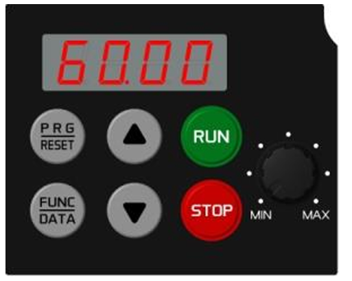
Setting up the reference frequency using the built-in potentiometer (factory default) Setting function code F001 to "4: Built-in potentiometer (POT)" (factory default) allows you to specify the reference frequency using the potentiometer.
Running/stopping the motor from keypad
By factory default, pressing the key RUN

starts running the motor in the forward direction and pressing the key STOP

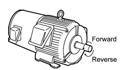
decelerates the motor to stop. The RUN key is enabled only in Running mode. By changing the setting of function code F002, you can change the starting direction of motor rotation; for example, you can have the motor start running in the reverse direction or in accordance with the wiring connection at the terminal block.
Rotation Direction of Motor, Specified by F002
Parameter | Name | Settings |
F002 | Operation Method | 0: RUN/STOP keys on keypad (Motor rotational direction specified by terminal command FWD/REV) 1: Terminal command FWD or REV 2: RUN/STOP keys on keypad (forward) 3: RUN/STOP keys on keypad (reverse) |
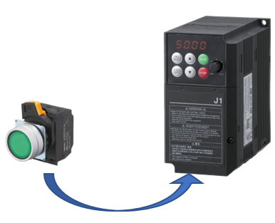
Start and stop from external inputs
In this example an external start and stop are used. Button is connected to run inverter forward. With reference frequency adjusted by potentiometer on keypad.
 Parameters
Select operation method to terminal command.
| Parameter | Name | Function |
| F001 | Frequency Command | 0: UP/DOWN keys on keypad 1: Voltage input to terminal [12] (0 to +10 VDC) 2: Current input to terminal [C1] (4 to 20 mA DC) 3: Sum of voltage and current inputs to terminals [12] and [C1] 4: Built-in potentiometer (POT) 7: Terminal command UP/DOWN control 9: Terminal command UP/DOWN control (ACC/DEC Time2) |
| F002 | Operation Method | 0: RUN/STOP keys on keypad (Motor rotational direction specified by terminal command FWD/REV) 1: Terminal command FWD or REV 2: RUN/STOP keys on keypad (forward) 3: RUN/STOP keys on keypad (reverse) |
| H008 | Rotational Direction Limitation | 0: Disable 1: Enable (Reverse rotation inhibited) 2: Enable (Forward rotation inhibited) |
Wiring
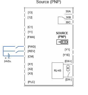
The button used in the example is a knob with two fixed positions. The power supply for the button is shown below both with the internal power supply and with an external power supply (PNP / SOURCE). When connected with an external power supply, SW1 must be set to SOURSE when PNP logic is to be used
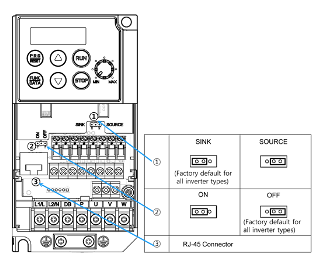
Internal power
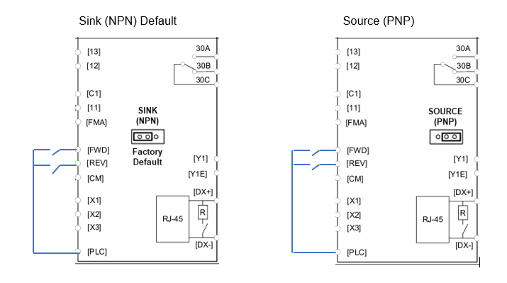
External power / PLC
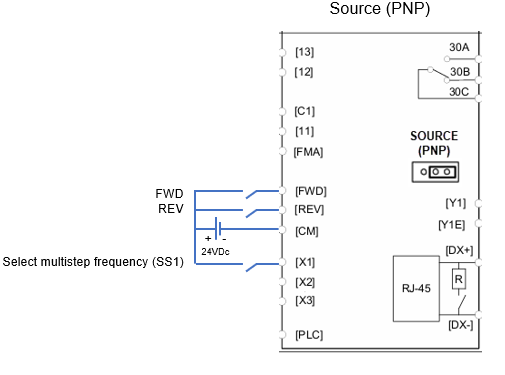
Start and stop from external inputs and high and low speed
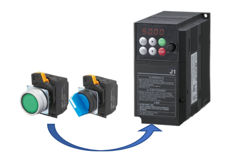
In this example an external start and stop are used. Button is connected to run inverter forward. With one reference frequency adjusted by UP/DOWN on keypad and the the other by parameter. Also another button to select between low and high speed. All terminals are default settings.
Select operation method to terminal command.
Parameter | Name | Function | |
F001 | Frequency Command | 0: UP/DOWN keys on keypad 1: Voltage input to terminal [12] (0 to +10 VDC) 2: Current input to terminal [C1] (4 to 20 mA DC) 3: Sum of voltage and current inputs to terminals [12] and [C1] 4: Built-in potentiometer (POT) 7: Terminal command UP/DOWN control 9: Terminal command UP/DOWN control (ACC/DEC Time2) | |
F002 | Operation Method | 0: RUN/STOP keys on keypad (Motor rotational direction specified by terminal command FWD/REV) 1: Terminal command FWD or REV 2: RUN/STOP keys on keypad (forward) 3: RUN/STOP keys on keypad (reverse) | |
H008 | Rotational Direction Limitation | 0: Disable 1: Enable (Reverse rotation inhibited) 2: Enable (Forward rotation inhibited) | |
E002 | Multistep Frequency 1 | 0.00 to 400.0 Hz | |
| |||
Parameter | Name | Function | |
E001 | Terminal [X1] Function | Selecting function code data assigns the corresponding function to terminals [X1] to [X3] as listed below. 0 (1000): Select multistep frequency (SS1) 1 (1001): Select multistep frequency (SS2) 2 (1002): Select multistep frequency (SS4) 3 (1003): Select multistep frequency (SS8) 4 (1004): Select ACC/DEC time (RT1) 6 (1006): Enable 3-wire operation (HLD) 7 (1007): Coast to a stop (BX) 8 (1008): Reset alarm (RST) 9 (1009): Enable external alarm trip (THR) 10 (1010): Ready for jogging (JOG) 11 (1011): Select frequency command 2/1 (Hz2/Hz1) 13: Enable DC braking (DCBRK) 17 (1017): UP (Increase output frequency) (UP) 18 (1018): DOWN (Decrease output frequency) (DOWN) 19 (1019): Enable data change with keypad (WE-KP) 20 (1020): Cancel PID control (Hz/PID) 21 (1021): Switch normal/inverse operation (IVS) 24 (1024): Enable communications link via RS-485 (LE) 33 (1033): Reset PID integral and differential components (PID-RST) 34 (1034): Hold PID integral component (PID-HLD) 90(1090) : Traverse On (TRV) 91(1091) : Traverse Up Offset (TRV UP_OFFSET) 92(1092) : Traverse Dn Offset (TRV DN_OFFSET) 97 (1097): Switch Operation Direction (DIR) Setting the value in parentheses ( ) shown above assigns a negative logic input (Active-OFF) to a terminal. Note that, in the case of THR, data "1009" is for normal logic (Active-ON) and "9," for negative logic (Active-OFF). Signals having no value in parentheses ( ) cannot be used for negative logic | |
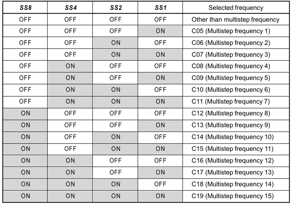
The combination of the ON/OFF states of digital input signals SS1, SS2, SS4 and SS8 selects one of 16 different frequency commands defined beforehand by 15 function codes C05 to C19 (Multistep frequency 0 to 15). With this, the inverter can drive the motor at 16 different preset frequencies.
The table below lists the frequencies that can be obtained by the combination of switching SS1, SS2, SS4 and SS8. In the "Selected frequency" column, "Other than multistep frequency" represents the reference frequency sourced by frequency command 1 (F001), frequency command 2 (C030), or others.
Wiring
The button used in the example is a knob with two fixed positions. The power supply for the button is shown below both with the internal power supply and with an external power supply (PNP / SOURCE). When connected with an external power supply, SW1 must be set to SOURSE when PNP logic is to be used.
External power / PLC
Start, stop (3-wire Input Function)
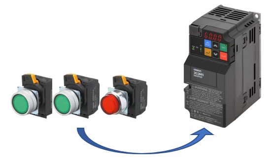
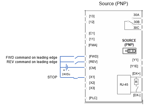
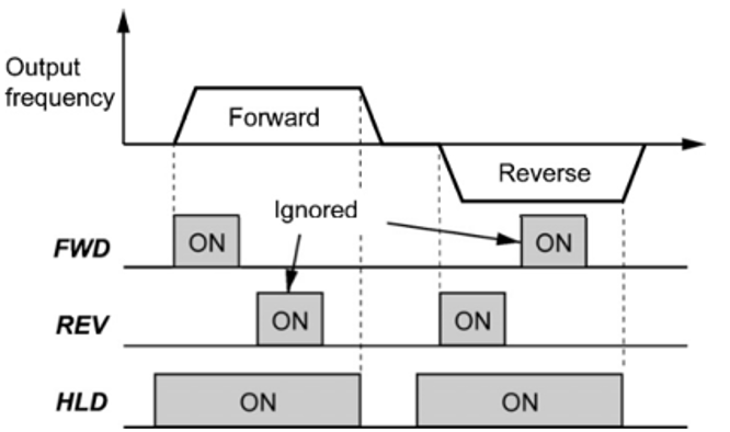
In this example command ON self-holds the forward FWD or reverse REV run command issued with it, to enable 3-wire inverter operation. HLD are used to self-hold run command.When HLD is ON it self-holds the first FWD or REV command at its leading edge. Turning HLD OFF releases the self holding. When HLD is not assigned, 2-wire operation involving only FWD and REV takes effect.
Parameters
Select operation method to terminal command.
method to terminal command
Parameter | Name | Function | |
F001 | Frequency Command | 0: UP/DOWN keys on keypad 1: Voltage input to terminal [12] (0 to +10 VDC) 2: Current input to terminal [C1] (4 to 20 mA DC) 3: Sum of voltage and current inputs to terminals [12] and [C1] 4: Built-in potentiometer (POT) 7: Terminal command UP/DOWN control 9: Terminal command UP/DOWN control (ACC/DEC Time2) | |
F002 | Operation Method | 0: RUN/STOP keys on keypad (Motor rotational direction specified by terminal command FWD/REV) 1: Terminal command FWD or REV 2: RUN/STOP keys on keypad (forward) 3: RUN/STOP keys on keypad (reverse) | |
H008 | Rotational Direction Limitation | 0: Disable 1: Enable (Reverse rotation inhibited) 2: Enable (Forward rotation inhibited) | |
E001
| Terminal [X1] Function | 6: Enable 3-wire operation (HLD) | |
| |||
Parameter | Name | Function | |
E001 E002 E003 | Terminal [X1-X3] Function | Selecting function code data assigns the corresponding function to terminals [X1] to [X3] as listed below. 0 (1000): Select multistep frequency (SS1) 1 (1001): Select multistep frequency (SS2) 2 (1002): Select multistep frequency (SS4) 3 (1003): Select multistep frequency (SS8) 4 (1004): Select ACC/DEC time (RT1) 6 (1006): Enable 3-wire operation (HLD) 7 (1007): Coast to a stop (BX) 8 (1008): Reset alarm (RST) 9 (1009): Enable external alarm trip (THR) 10 (1010): Ready for jogging (JOG) 11 (1011): Select frequency command 2/1 (Hz2/Hz1) 13: Enable DC braking (DCBRK) 17 (1017): UP (Increase output frequency) (UP) 18 (1018): DOWN (Decrease output frequency) (DOWN) 19 (1019): Enable data change with keypad (WE-KP) 20 (1020): Cancel PID control (Hz/PID) 21 (1021): Switch normal/inverse operation (IVS) 24 (1024): Enable communications link via RS-485 (LE) 33 (1033): Reset PID integral and differential components (PID-RST) 34 (1034): Hold PID integral component (PID-HLD) 90(1090) : Traverse On (TRV) 91(1091) : Traverse Up Offset (TRV UP_OFFSET) 92(1092) : Traverse Dn Offset (TRV DN_OFFSET) 97 (1097): Switch Operation Direction (DIR) Setting the value in parentheses ( ) shown above assigns a negative logic input (Active-OFF) to a terminal. Note that, in the case of THR, data "1009" is for normal logic (Active-ON) and "9," for negative logic (Active-OFF). Signals having no value in parentheses ( ) cannot be used for negative logic | |
Wiring
The button used in this example for running inverter FWD /REV are instantaneous button. Stop button are two fixed positions .
Use external brake
The J1 series Inverter has a built-in function for controlling an external brake, used,
for example, in a hoist system.
The Inverter's function is to manage the activation and deactivation of the output
that controls this mechanical brake, based on the motor's operating conditions:
the output is activated when the output frequency drops below a certain preset
threshold, which means the motor is about to stop.
Note: This function can always be used, regardless of the type of control specified
in the parameter F042.
To enable this feature, you must first assign function 57: BRKS, which is related to
brake control, to a digital output:
• E027 = 57 (relay output 30A)
or
• E020 = 57 (transistor output Y1)
Note: It is recommended to use transistor connected to externa relay.
The following parameters are used to define the brake output intervention times
when the RUN command is given and the Inverter starts to accelerate the motor:
• J068 brake-release current: the brake output drops when the current
supplied by the Inverter exceeds a certain value. Using this parameter, it is
possible to set this current threshold expressed as a % of the motor's nominal
value (P003); default value 100%.
• J069 brake-release frequency: when the frequency supplied by the Inverter
exceeds this threshold, the brake output is deactivated; default value 1 Hz.
• J070 Brake-release timer: starts from the moment the Inverter detects that
the current exceeds the value indicated in parameter J068; default value 1
sec.
Similarly, there are the other three parameters that manage the brake in the
opposite situation, that is when the RUN command is removed and the Inverter
decelerates the motor:
J071 brake-applied frequency: when the motor is decelerating and the
output frequency from the inverter drops below this value, the brake output
is activated; default value 1 Hz.
• J072 brake-applied time: time between the moment the frequency drops
below the value indicated by J071 and the moment the brake output is
activated; default value 1 sec.
The Inverter inputs cannot receive the feedback signal that indicates brake
release.
If such comprehensive brake management is not required, it can still be
controlled simply by checking a threshold related to the output frequency.
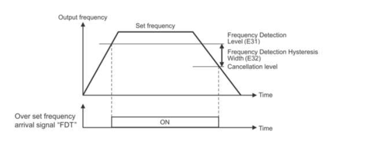
It is possible to generate an output signal (E020, E027 with value 2), which is output
when the output frequency becomes equal to or greater than the threshold
specified in parameter E031. In addition, the width of the frequency detection
hysteresis (parameter E032) can also be defined.
Below is a graphical representation of this function:
Was this article helpful?
That’s Great!
Thank you for your feedback
Sorry! We couldn't be helpful
Thank you for your feedback
Feedback sent
We appreciate your effort and will try to fix the article