Configuration of analog modules
CJ1W-AD0?1(-V1)
CJ-series cards/modules are divided into three main groups:
- Standard I/O modules
- Special I/O (SIOU) modules
- CPU bus modules.
Analog cards fall under the Special I/O module group.
Indicators on the CJ1W-AD0X1:
| Name | Color | Description |
| RUN | Green | Lit during normal operation |
| ERC | Red | Indicates configuration fault(s) |
| ERH | Red | Indicates hardware fault(s) |
| ADJ | Yellow | Flashing during calibration-mode |
Wiring of the cards: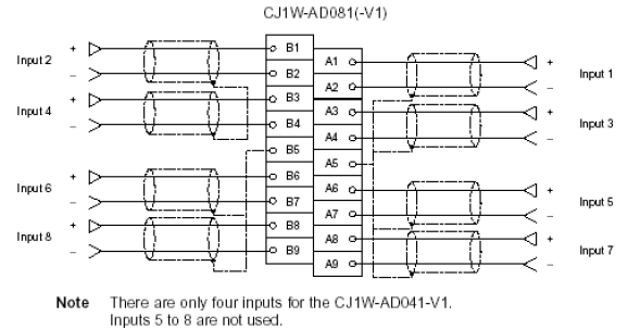
Front view of the cards:
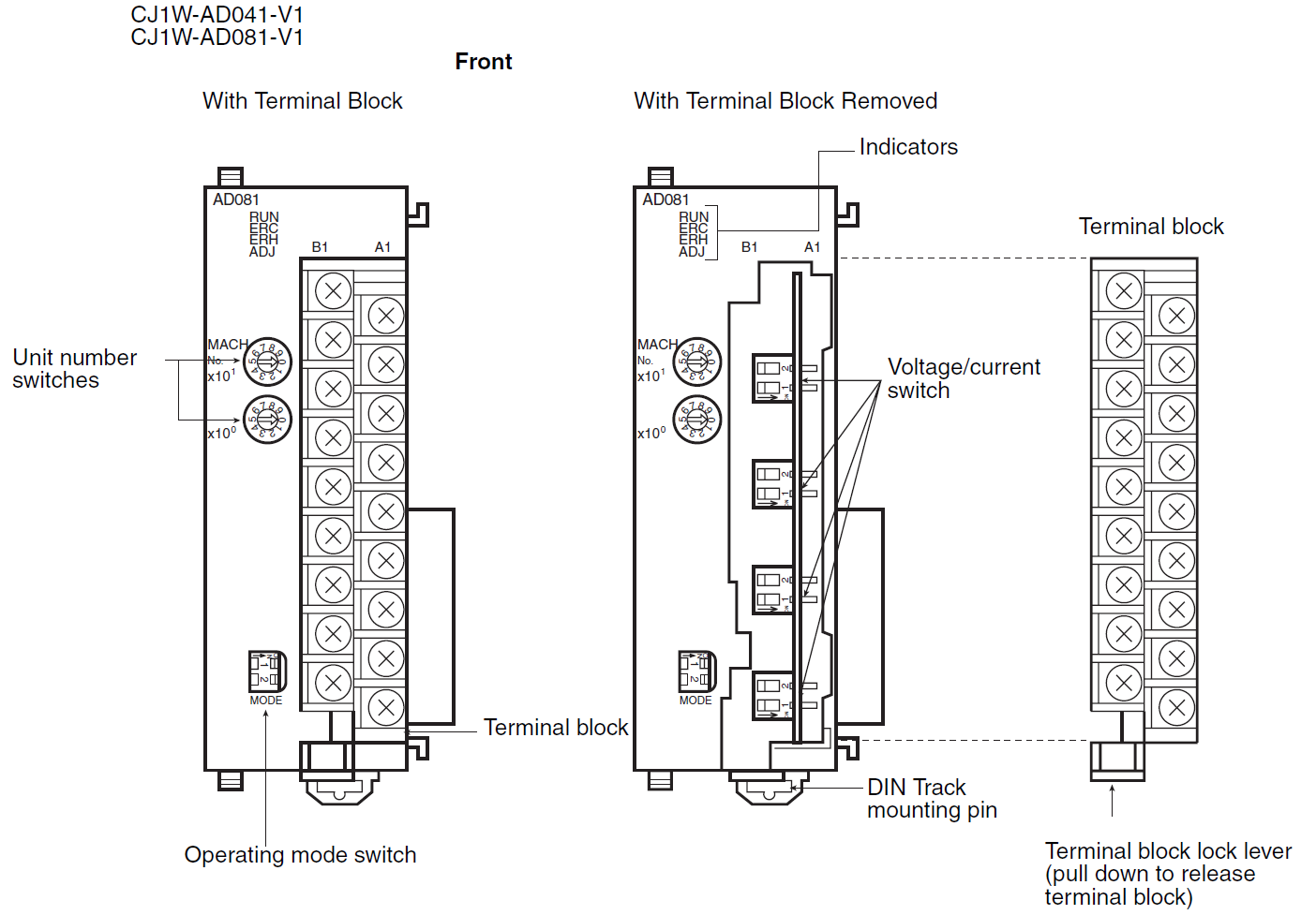
Setting of the rotary switches:
Set the desired module number (MACH No.) using the rotary number switches on the front of the module. No special modules may share the same module number. Each module requires/reserves two fixed areas in the PLC memory. These areas depend on the selected module number.
Memory allocation example:
The following two memory areas are occupied by
the analog module:
CIO 2XY0–2XY9 and D2XY00–D2XY99
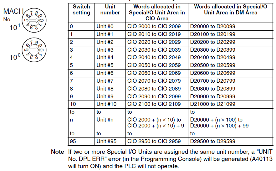
Example: Switch ×10^ 1 (X) = 3 and switch ×10^ 0 (Y) = 1
This would result in module number (MACH No.) 31 and memory allocation CIO 2310–2319 and D23100–23199.
Setup through the IO-table:
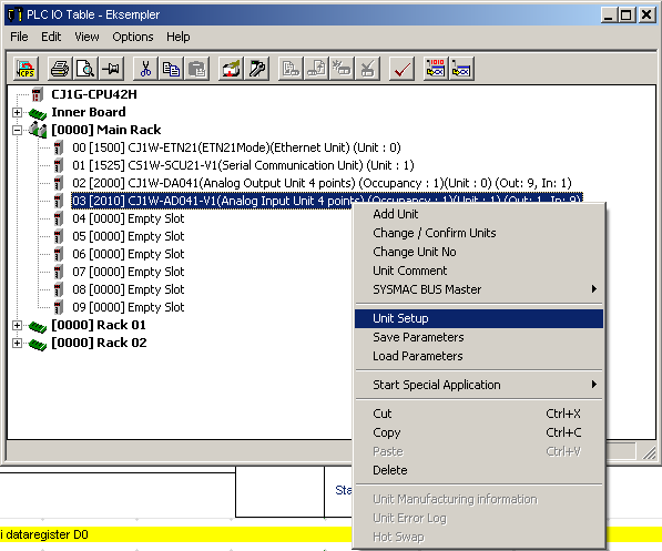
By opening the IO table in the project tree, you can double-click on the AD card and make adjustments before downloading to the card.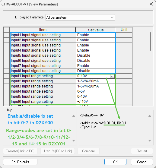
Setup through code:
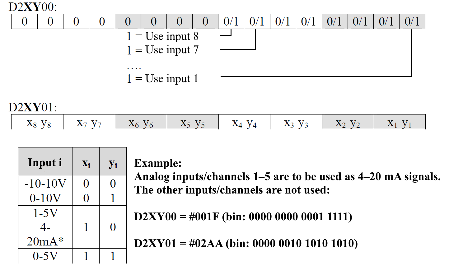
As seen above. All of the settings have their place in the D2XY00 memory.
By writing enable/disable to the D2XY00 word and range-codes to the D2XY01 word you can set the card up through code. This will make your application more reliable as the user don't have to use the IO-table and download new settings if a card needs replacement.
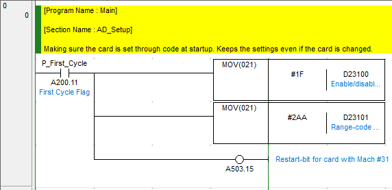
Actual ladder-code for an AD081-V1 with Mach nr. #31. 5 inputs enabled and 4-20mA:
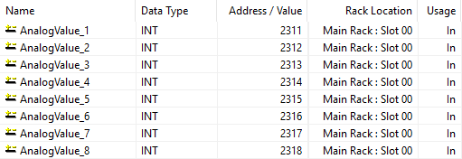
The analogue input addresses:
The actual input value ends up in CIO2XX1->. So for our Card #31 this will be:
Was this article helpful?
That’s Great!
Thank you for your feedback
Sorry! We couldn't be helpful
Thank you for your feedback
Feedback sent
We appreciate your effort and will try to fix the article