There are two types of ten-key switches, one that uses binary code and strobe signals, and another that uses decimal code. This document introduces programming for the ten-key switch that uses decimal code.
Program and Operation
1. Ten-key Input Allocations and the Data Storage Area
System Specifications
Up to 4 digits of model data from the ten-key switch is input to CIO 0 bits 00 to 09 and moved to D102.
The numbers stored in D102 are shifted 1 digit (4 bits) to the right whenever numbers are input using the ten-key. If 5 or more digits are input, then the numbers stored in D102 will be deleted one-by-one sequentially for every digit input starting with the leftmost bit.
Ten-key input
CIO 0.00: Key 0
CIO 0.01: Key 1
CIO 0.02: Key 2
(to)
CIO 0.09: Key 9
Data storage area
D101: Ten-key data buffer area
D102: Ten-key data storage area
2. Ladder program
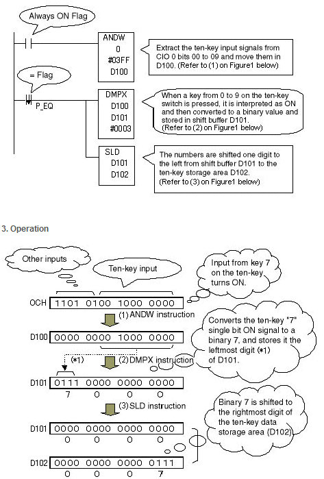
Note:
1.If 5 or more digits are input using the ten-key, then by changing the second operand (shift leftmost word) of the ONE DIGITS SHIFT LEFT (SLD) instruction, the number of useable digits can be extended in 4 digits units.
2.Using the TEN KEY INPUT instruction with the CQM1H Programmable Controllers or C200HX/HG/HE Programmable Controllers will allow a maximum of 8 digit to be input from the ten-key.
Was this article helpful?
That’s Great!
Thank you for your feedback
Sorry! We couldn't be helpful
Thank you for your feedback
Feedback sent
We appreciate your effort and will try to fix the article