Introduction
This article provides an overview of the available GRT1 Communication Units and their I/O Allocation specification.
I/O Allocation
There are restrictions on the number of SmartSlice I/O Units that you can connect to one Communications Unit.
The specification for each GRT1 Communication Unit is shown in the table below.
| Model name | GRT1-PRT | GRT1-PNT | GRT1-DRT | GRT1-CRT | GRT1-ML21 | GRT1-ECT |
| Network Specification | Profibus DP | PROFINET IO | DeviceNet | CompoNet | Mechatrolink-II | EtherCAT |
| Number of I/O data | ||||||
| Max. Input: | 128 bytes | 32 bytes | 128 bytes | 64 bytes | ||
| Max. Output: | 128 bytes | 32 bytes | 128 bytes | 64 bytes | ||
| Max. I/O Allocation: | 128 bytes | 64 bytes | 128 bytes | 128 bytes | ||
|
Number of I/O points |
1024 I/O | 256 Inputs and 256 Outputs |
1024 I/O | 512 Inputs and 512 Outputs |
||
|
Number of connectable |
Up to 642 |
|||||
Note 1: The GRT1-ML2 supports the GRT1-IA4-1, GRT1-IA4-2, GRT1-OD4G-3, GRT1-TS2P, GRT1-TS2K and GRT1-TS2T slice units only in combination with TJ2-MC64 motion controller. They are not supported in combination with TJ1-MC16/04.
Note 2: GRT1-END-M end plate for PROFINET name storage counts as a unit, it reduces the total amount of connectable SmartSlice I/O Units to 63.
Configuration examples
The following examples provide information about the I/O Allocation with GRT1 Units regarding permitted and bad configurations. These examples visualise what could happen with the I/O Allocation.
Permitted Configuration:
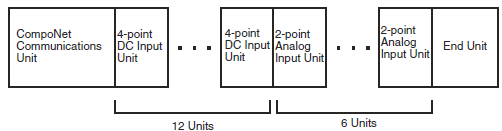
Note: GRT1-CRT used as coupler
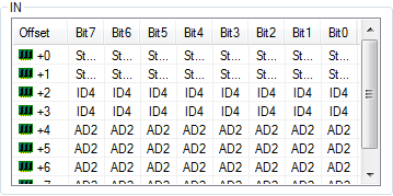
- 2 bytes are used for CompoNet Communications Unit status
- Four-point DC Input Unit (GRT1-ID4): 4 bits × 12 = 6 bytes in Input Area
- Analog Input Unit (GRT1-AD2): 2 words (4 bytes) × 6 = 24 bytes in Input Area
- Total: 32 bytes in Input Area
The I/O Allocation is shown below.
Bad Configuration:
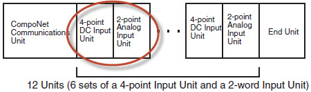
Note: GRT1-CRT used as coupler
- 2 bytes are used for CompoNet Communications Unit status
- Four-point DC Input Unit (GRT1-ID4): 4 bits x 6 = 3 bytes in Input Area
- Two-point Analog Input unit (GRT1-AD2): 2 Words (4 bytes) x 6 = 24 bytes in Input Area
- Total: 29 bytes + 9 unused bytes = 38 bytes in Input Area
A section of the unused bytes in the I/O Allocation are shown below.
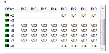
The reason that bits 4 to 7 are not used and the GRT1-AD2 does not start at byte 3 is that: “I/O Units with bit allocations (such as the GRT1-ID4/OD4) are allocated data in 2-bit units. I/O Units with word allocations (such as the GRT1-AD2) are allocated data in 1-word units and are allocated at even byte boundaries.”
Please refer to chapter 2-2 Unit Numbers and I/O Allocations of Operation Manual ‘Slice I/O Units’ (Cat. No. W455-E1-06) for more details.
Was this article helpful?
That’s Great!
Thank you for your feedback
Sorry! We couldn't be helpful
Thank you for your feedback
Feedback sent
We appreciate your effort and will try to fix the article