Introduction
The FINS network address consists of 3 fields:
The No. 0 is reserved for the CPU
The header of the FINS framework includes the FINS address of the recipient and sender.
In the example below,
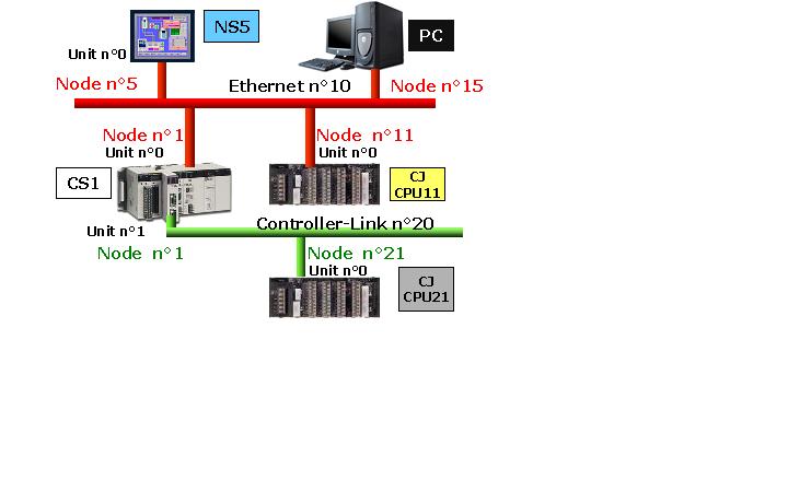
a command from the PC for the CJ-CPU21 will be:
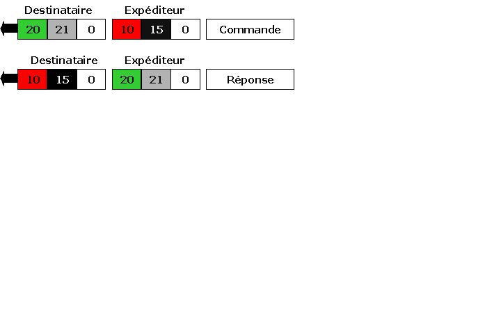
Imperative routing:
1 - The network cards must be associated with a network number with a local routing table.
2 - Bridges (here CS1) must be declared in the routing tables of all participants (NS, CJ-CPU11,-CPU21 CJ).
II. Network configuration
PLC Configuration
1. Configure the Ethernet card in the PLC (see article Login/Configuration of CS/CJ ETN21)
2. Start the network configuration CX-Net project from your CX-Integrator (Tools menu) or directly from the menu: Start \ Program \ Omron \ CX-One \ CX-Programmer \ Network Configuration Tool CX-Net.
CS1 Configuration
1. Right click on Unit 00, No. Allow network (Ethernet = 10)
2. Right click on Unit 01, No. Allow network (Controller-Link = 20).
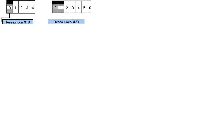
3. Move the routing table in the PLC
CJ1-CPU11 Configuration
1. Right click on Unit 00, No. Allow network (Ethernet = 10)
2. Right click on the fields LAN # xx, add the CS1 PLC gateway to the network-Link Controller (the CJ1 not seen locally).
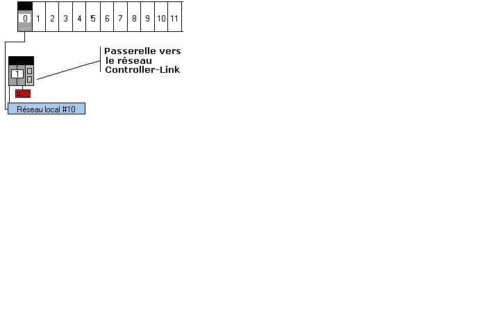
3. Transfer the routing table in the PLC
CJ1-CPU21 Configuration
1. Right click on Unit 00, No. Allow network (Controller-Link = 20)
2. Right click on the fields LAN # xx, add the CS1 PLC gateway to the Ethernet network (the CJ1 not seen locally).
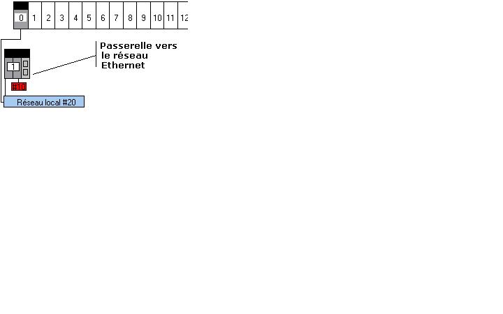
Configuration of the NS
1. Start CX-Designer
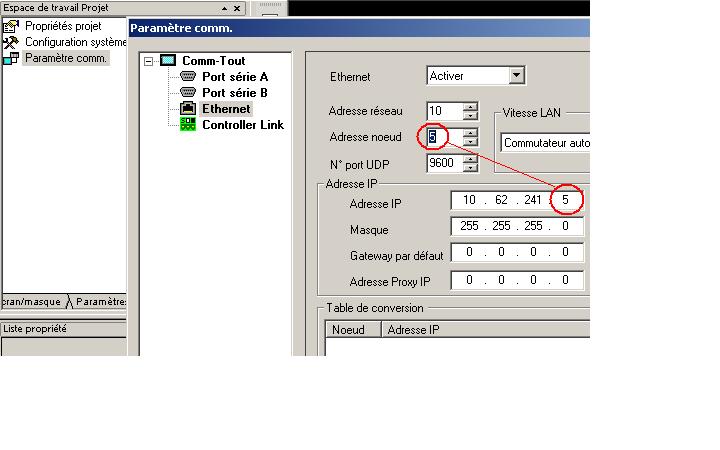
2. Turn on the Ethernet interface
3. Allow No Network Interface Ethernet (No. 10)
4. Fill in the IP field. No. Use a node identical to the last field of the IP address.
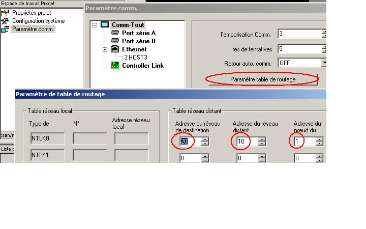
5. Return to the main item (comm-All) and add the gateway (CS1) on the LAN (10) to the Controller-Link (20)
6. Perform a rapid transfer of the project. The network is now operational.
Was this article helpful?
That’s Great!
Thank you for your feedback
Sorry! We couldn't be helpful
Thank you for your feedback
Feedback sent
We appreciate your effort and will try to fix the article