- - Speed feedback for an axis is just a calculation
- - The quicker the cycle time, the larger the scaling factor use for the calculation to scale to units per second
- - The lower encoder resolution, the more inaccuracy of each position pulse
Example:
| Drive: | G5 Servo |
| Units of display: | degree |
|
Command pulse count |
1048576 pulse/rev |
| Work travel distance: | 36 |
This means that:
resolution => (36 deg/rev) / (1048576 pulse /rev) = 0.00003433 deg/pulseLet's analyse how the monitoring speed is changing when using different cycles, 1ms and 2ms:
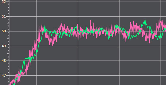
The speed is changing by1 pulse:
(0.00003433 deg/pulse) x 1  pulse /  1 ms  =  + 0.03433 deg/s (pink)

(0.00003433 deg/pulse) x 1  pulse /  2 ms  =  + 0.01716 deg/s (green)
So the smallest change in speed can appear much larger that the resolution of the position counts.
|
|
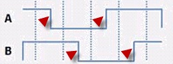
Additionally a common mistake is to enter the encoder resolution as it is, without taking into account that the GX counts 4 rise/falling edges per pulse by default. If the encoder manual states 2000 incr/revolution, GX-EC02XX could count 4 x 2000 = 8000. |
 |

Solution
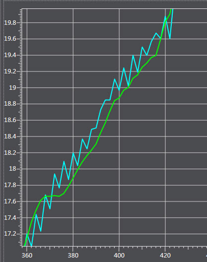
To minimize this effect, a monitoring filter on axis configuration can be used to calculate a running average. For instance if you set on MC_AX000

filter = 0 (blue)
filter = 4. (green)
Was this article helpful?
That’s Great!
Thank you for your feedback
Sorry! We couldn't be helpful
Thank you for your feedback
Feedback sent
We appreciate your effort and will try to fix the article