Introduction
1. 1-axis configuration:
The arrangement of the CW and CCW limit switch (limit signal left and right) and the near zero-limit switch for the 1-axis positioning example the spindle drive:
2. Definition of Zero Search
1) The zero Origin Search is done at the edge of limit s / w of CCW limit
2) Origin of the zero location is triggered by Origin Near limit s / w turning off
3. Operation
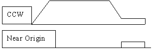
1)Between the tool close to the zero-switch and CW limit switch
If the near zero-limit switch is approached, it is at the speed of 2000 p / s to 100 p / s.
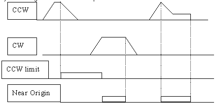
2) Tool between zero and near-limit switch-CCW limit switch
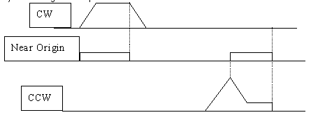
3) Tool at near zero-limit switch
3. I / O signals
Inputs
0001 = CCW limit switch
0002 = CW limit switch
0008 = close to zero
Over 0010 = Heat input
0012 = reset feedback signal
0013 = Tip-link input operation run (CW)
0014 = Tip-operation input Clockwise (CCW)
0015 = command 'zero search'
Outputs
1001 = Current Output OFF
1002 = Heat Over displayname
1008 = Zero Search
1009 = zero found
1600 = CCW Tip-stop operation
1601 = CW Operation Tip Stop
1602 = Zero-Stop Search
4. PLC settings:
1) pulse output operation DM6611 = 0001
2) Pulse Setting the Interface 1: Linear mode, standard pulse output, only software reset = DM6643 # 0012
3) The words 233 and 232 in I / O memory area of the PLC include the counter value
4) settings for the origin Search:
DM0000 = # 0005 (Acceleration = 50 pulse / 4.08ms)
DM0001 = # 0200 (zero-speed search k = 2 pulse / sec)
DM0002 = # 0005 (braking = 50 pulse / 4.08ms)
DM0003 = # 0010 (zero-search convergence speed = 100 pulse / sec)
5. Attached Zero search, PLC program below.
Was this article helpful?
That’s Great!
Thank you for your feedback
Sorry! We couldn't be helpful
Thank you for your feedback
Feedback sent
We appreciate your effort and will try to fix the article