Objectives
To enable the configuration of the ETN21 card via internet connection
Introduction
Remote assistance via TCP/IP. Please note all screenshots are based on an Italian machine.
Content
1 NAT (network address translation)
It's enough to have public IP addresses for the router alone, in this case where the IP addresses of a subnet are not visible to other subnets, the traffic is normally directed to the router, which will route packets with certain characteristics to the node required. Usually the packages sent to certain TCP or UDP ports are redirected to the specific private IP addresses. NAT systems are used to share Internet access with all the nodes that make up a local network, which is almost exclusively outgoing traffic, ie originating from the inside, typically generated by the applications client. To allow incoming traffic to the server, nodes can be used for the mapping of IP addresses or the mapping of IP ports. In the first case additional public IP addresses are required to be mapped out of private IP addresses inside the network. In the second case they are not needed, the mapping is done by sending packets to a given TCP or UDP port to a specific node of the IP network. In this instance we can map the UDP port 9600 (Communication FINS) Local IP Address PLC.
It's enough to have public IP addresses for the router alone, in this case where the IP addresses of a subnet are not visible to other subnets, the traffic is normally directed to the router, which will route packets with certain characteristics to the node required. Usually the packages sent to certain TCP or UDP ports are redirected to the specific private IP addresses. NAT systems are used to share Internet access with all the nodes that make up a local network, which is almost exclusively outgoing traffic, ie originating from the inside, typically generated by the applications client. To allow incoming traffic to the server, nodes can be used for the mapping of IP addresses or the mapping of IP ports. In the first case additional public IP addresses are required to be mapped out of private IP addresses inside the network. In the second case they are not needed, the mapping is done by sending packets to a given TCP or UDP port to a specific node of the IP network. In this instance we can map the UDP port 9600 (Communication FINS) Local IP Address PLC.
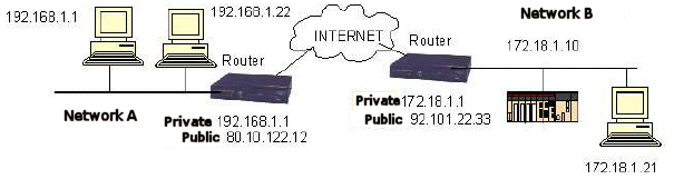
NETWORK A
â— Network Address 192.168.1.0
â— Subnet Mask 255.255.255.0
â— Router, private address 192.168.1.1 (Gateway)
â— Router, public address 80.10.122.12
NETWORK B
â— Networ Address 172.18.1.0
â— Subnet Mask 255.255.255.0
â— Router, private address 172.18.1.1 (Gateway)
â— Router, public address 92.101.22.33
â— PLC Address 172.18.1.10
In the case of direct connection of PC to the Internet, the network parameters should be assigned
dynamically by the ISP.
â— Network Address 192.168.1.0
â— Subnet Mask 255.255.255.0
â— Router, private address 192.168.1.1 (Gateway)
â— Router, public address 80.10.122.12
NETWORK B
â— Networ Address 172.18.1.0
â— Subnet Mask 255.255.255.0
â— Router, private address 172.18.1.1 (Gateway)
â— Router, public address 92.101.22.33
â— PLC Address 172.18.1.10
In the case of direct connection of PC to the Internet, the network parameters should be assigned
dynamically by the ISP.
1.1 PLC Configuration
Select the Ethernet card from the table I / O of the PLC and access the menu card configuration.
Select the Ethernet card from the table I / O of the PLC and access the menu card configuration.
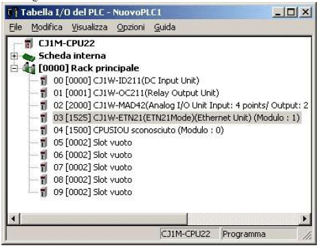
Setting the IP parameters of the card
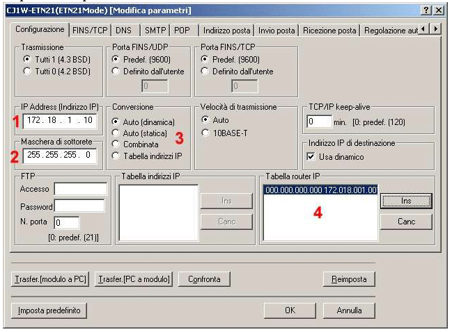
1. IP address of the PLC, the IP address is 172.18.1.10
2. Netmask for the private network router, set the value assigned to
Network B, in our example 255.255.255.0
3. Set the conversion to "Auto (Dynamic)"
4. Complete the table for the assigned router IP address of the Gateway.
2. Netmask for the private network router, set the value assigned to
Network B, in our example 255.255.255.0
3. Set the conversion to "Auto (Dynamic)"
4. Complete the table for the assigned router IP address of the Gateway.
Setting the Gateway network.
Click the "Insert" button on the "Table router IP" panel.
Click the "Insert" button on the "Table router IP" panel.
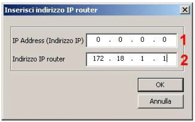
1. Enter the address 0.0.0.0, so all the traffic directed to a non-local network address is the router.
2. Enter the IP address assigned to the router on the local network. In the case of Network B
example, set 172.18.1.1
2. Enter the IP address assigned to the router on the local network. In the case of Network B
example, set 172.18.1.1
1.2 Setting the CX-Programmer
Referring to the network, communication with CX-Programmer, will be configured as follows.
Referring to the network, communication with CX-Programmer, will be configured as follows.
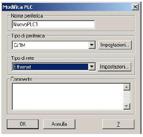
Select the type of network, "Ethernet" is mapped to UDP port 9600
or "Ethernet (FINS / TCP) to use the TCP protocol, in this case it is
necessary to map the TCP port 9600. It is important to select the protocol dependant on the configuration of the router.
or "Ethernet (FINS / TCP) to use the TCP protocol, in this case it is
necessary to map the TCP port 9600. It is important to select the protocol dependant on the configuration of the router.
Select "Settings" and the "Network" table
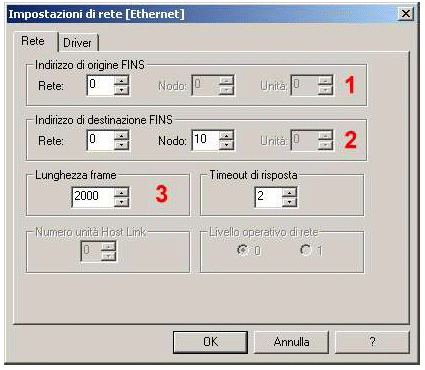
1. The number of FINS origin networks must match that set in the routing table of the PLC to the Ethernet network. If the table is not present or the PLC is
directly connected to the router you can set 0 as the network number.
2. The number of FINS destination networks must match that set in the routing table of the PLC communication card. If the table is not
present or the PLC is connected directly to the router it can be set as 0 network number. The node number must be equal to the node number set on the PLC card.
3. It may be necessary to change the frame length according to the size of the maximum package supported by the connection with the provider, this
parameter is called MTU. When using the UDP protocol,frame length is always less than or equal to the MTU.
It might also be necessary to increase the timeout.
directly connected to the router you can set 0 as the network number.
2. The number of FINS destination networks must match that set in the routing table of the PLC communication card. If the table is not
present or the PLC is connected directly to the router it can be set as 0 network number. The node number must be equal to the node number set on the PLC card.
3. It may be necessary to change the frame length according to the size of the maximum package supported by the connection with the provider, this
parameter is called MTU. When using the UDP protocol,frame length is always less than or equal to the MTU.
It might also be necessary to increase the timeout.
Select the "Driver" tab.
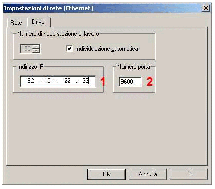
1. Here set the public IP address assigned to the router, 92.101.22.33
2. Set the number of the TCP or UDP port that has been mapped to the IP address of the PLC. If your network router has more than one PLC it is necessary to map the many ports to however many PLCs are connected. Selecting the PLC to connect to is enough change the port number. The number of FINS destination nodes must be amended accordingly.
Was this article helpful?
That’s Great!
Thank you for your feedback
Sorry! We couldn't be helpful
Thank you for your feedback
Feedback sent
We appreciate your effort and will try to fix the article