The wiring for the self-holding circuit is eliminated in order to eliminate one wire between the 61F and the electrodes. (The electrode itself is not eliminated.)
Precautions:
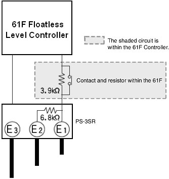
Two resistors are connected in series: a 6.8 kΩ resistor in the Electrode Holder and 3.9 kΩ resistor in the 61F Controller.
Even if the rising water submerges E2, the resistance will be 6.8 kΩ + 3.9 kΩ = 10.7 kΩ, so the Controller's circuit will not operate. If the water reaches E1, the resistance will be only 3.9 kΩ, so the Controller's circuit will operate and the internal relay contacts will switch. When the water level falls below E1, there is still a resistance of 6.8 kΩ from E2 at the Controller's contact, so the relay is held.
Precautions:
- Even though a Controller is called a Two-wire Controller (such as the 5-wire 61F-G3N becoming a 4-wire 61F-G3NR), the actual wiring is not necessarily limited to just two wires.
- A Two-wire Electrode Holder (with a model number ending in R) is required for a two-wire circuit.
Two resistors are connected in series: a 6.8 kΩ resistor in the Electrode Holder and 3.9 kΩ resistor in the 61F Controller.
Even if the rising water submerges E2, the resistance will be 6.8 kΩ + 3.9 kΩ = 10.7 kΩ, so the Controller's circuit will not operate. If the water reaches E1, the resistance will be only 3.9 kΩ, so the Controller's circuit will operate and the internal relay contacts will switch. When the water level falls below E1, there is still a resistance of 6.8 kΩ from E2 at the Controller's contact, so the relay is held.
Was this article helpful?
That’s Great!
Thank you for your feedback
Sorry! We couldn't be helpful
Thank you for your feedback
Feedback sent
We appreciate your effort and will try to fix the article