Introduction
This tutorial supplements the original manuals. Use it to familiarize yourself with products, not as a complete installation guide. Information sources: I532 Sysdrive RV User's Manual I537 Sysdrive PV User's Manual
Custom curve: E1-03=F, configure E1-04-E1-13 Key Parameters
Error CodesCritical errors halt operation, activate alarms. Reset via S3-S7 (H1-01-05=14), RESET button, or power cycle.
Product Information RV (advanced) and PV (simplified) drives. PV for fans/pumps, RV for demanding applications. Inverter Assembly Mechanical Clearances: 120mm above/below, 30mm sides. Electrical

- Set tension band properly (≥75kW models)
- Install brake resistance for high-load braking
- Use Remote Emergency Stop circuit meeting current criteria
- External web filters required (available separately). Minimize distance between filter output and inverter input.
- Motor cables require 90° merging for EMC. Use ferrite rings and EMC nipple grounding.
- 7 digital 24VDC inputs (5 configurable via H1-01-05)
- 4 digital relays (3 for PV). MA/MB/MC indicates errors/alarms
- Analog reference: 0-10V (A1-AC) or 4-20mA (A2-AC). Potentiometer: V+ → A1 → VC
- Pulse control available on RV (RP-AC, H6-01)
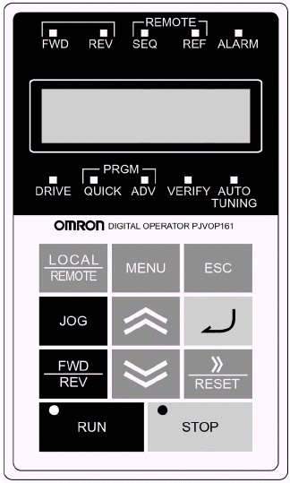 | FWD: S1 active REV: S2 active Seq: Digital control REF: Analog rate ALARM: Error detected DRIVE: Operation mode QUICK: Simple programming Adv: Advanced programming Verify: Changed parameters AUTO TUNING: Motor calibration LOCAL/REMOTE: Toggle MENU: Top ESCAPE: Up JOG: Local jog FWD/REV: Direction RUN: Start STOP: Halt >>/RESET: Toggle/reset ENTER: Select/set ▲/▼: Navigate |
STOP (red) lit standby, RUN (green) lit operating
Mode Overview
| Operating | Run/monitor only |
| Simple Programming | Common parameters |
| Advanced Programming | All parameters |
| Verification | Changed parameters |
| Auto Tuning | Motor calibration |
Use MENU to cycle modes, ENTER to select. Blinking values editable. >> toggles fields, ESC exits.
Parameter Settings Initialization/Privileges Factory reset: A1-03=2220. Access: A1-01 (0=unlocked). Password: A1-05 (set via A1-04 + RESET+MENU). Management Method Control source: b1-02 (1=digital default). 2-wire (S1/S2) vs 3-wire (S1/S2/S5) via A1-03 (2220/3330). Frequency reference: b2-01. V/f Curve
| E1-03 | Type | Application | Max Freq |
|---|---|---|---|
| 0-3 | Constant Torque | Standard | 50-72Hz |
| 4-7 | Variable Torque | Pumps/fans | 50-60Hz |
| 8-B | High Start Torque | Cranes/long cables | 50-60Hz |
| C-E | High Frequency | >60Hz output | 90-180Hz |
| Parameter | Description | Default |
|---|---|---|
| A1-02 | Control Method (0=V/f) | 0 |
| b1-01 | Reference Source | 1 (Analog) |
| b1-02 | Operation Source | 1 (Digital) |
| b1-03 | Stop Method | 0 (Ramp) |
| C1-01/02 | Accel/Decel Time (s) | 10.0 |
| E1-03 | V/f Curve | F |
| E2-01 | Motor Rated Current | Model-based |
| L2-01 | Undervoltage Response | 0 |
| Code | Description |
|---|---|
| oC | Over Power (>200%) |
| GF | Earth Fault |
| PUF | Fuse Failure |
| ou | Overvoltage (DC bus) |
| Uu1/2 | Undervoltage |
| OH1 | Heat Sink Overheat |
| oL1-3 | Overload |
| EF | Remote Error |
| oPr/CPFxx | Control Panel Error |
Was this article helpful?
That’s Great!
Thank you for your feedback
Sorry! We couldn't be helpful
Thank you for your feedback
Feedback sent
We appreciate your effort and will try to fix the article