Introduction
- Set tension band properly (≥75kW models)
- Install brake resistance for high-load braking
- Use Remote Emergency Stop circuit meeting current criteria
- External web filters required (available separately). Minimize distance between filter output and inverter input. Note cumulative ground leakage current risks.
- Motor cables require 90° merging for EMC. Use ferrite rings (3 leads, 2 loops) and EMC nipple grounding. Avoid routing earth leads through ferrite rings.
- 7 digital 24VDC inputs (5 configurable via H1-01-05)
- 4 digital relays (3 for PV). MA/MB/MC indicates errors/alarms
- Analog reference: 0-10V (A1-AC) or 4-20mA (A2-AC). Potentiometer: V+ → A1 → VC
- Pulse control available on F7 (RP-AC, H6-01)
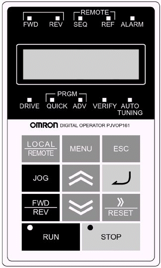 | FWD: S1 active REV: S2 active Seq: Digital input control REF: Analog rate set ALARM: Error detected DRIVE: Operation mode QUICK: Simple programming Adv: Advanced programming Verify: Changed parameters AUTO TUNING: Motor calibration LOCAL/REMOTE: Control toggle MENU: Top menu ESCAPE: Menu up JOG: Local mode jog FWD/REV: Direction set RUN: Local start STOP: Local stop >>/RESET: Toggle/reset ENTER: Select/set ▲/▼: Navigate/change |
STOP (red) lit in standby, RUN (green) lit during operation
Mode Overview
| Operating | Run/monitor only |
| Simple Programming | Common parameters |
| Advanced Programming | All parameters |
| Verification | Changed parameters |
| Auto Tuning | Motor vector calibration |
Use MENU to cycle modes, ENTER to select. Blinking values are editable. Use >> to toggle fields, ESC to exit.
Parameter Settings Initialization/Privileges Reset to factory defaults: Set A1-03=2220. Access level: A1-01 (0=unlocked, 2=locked). Password: A1-05 (set via A1-04 + RESET+MENU).
Management Method Control source: b1-02 (1=digital inputs default). 2-wire (S1/S2) vs 3-wire (S1/S2/S5) set via A1-03 (2220/3330). Frequency reference: b2-01.
V/f Curve
| E1-03 | Type | Application | Max Freq |
|---|---|---|---|
| 0-3 | Constant Torque | Standard apps | 50-72Hz |
| 4-7 | Variable Torque | Pumps/fans | 50-60Hz |
| 8-B | High Start Torque | Long cables/cranes | 50-60Hz |
| C-E | High Frequency | >60Hz output | 90-180Hz |
Custom curve: Set E1-03=F and configure E1-04-E1-13
Key Parameters
| Parameter | Description | Default |
|---|---|---|
| A1-02 | Control Method (0=V/f, 2=Vector) | 0 (F7:2) |
| b1-01 | Reference Source (1=Analog) | 1 |
| b1-02 | Operation Source (1=Digital) | 1 |
| b1-03 | Stop Method (0=Ramp) | 0 |
| C1-01/02 | Accel/Decel Time (s) | 10.0 |
| E1-03 | V/f Curve (F=Custom) | F |
| E2-01 | Motor Rated Current | Model-based |
| L2-01 | Undervoltage Response | 0 |
Error Codes Critical errors halt operation and activate alarm relay. Reset via S3-S7 (H1-01-05=14), RESET button, or power cycle.
| Code | Description |
|---|---|
| oC | Over Power (>200%) |
| GF | Earth Fault |
| PUF | Fuse Failure |
| ou | Overvoltage (DC bus) |
| Uu1/2 | Undervoltage (DC/control) |
| OH1 | Heat Sink Overheat |
| oL1-3 | Motor/Inverter Overload |
| EF | Remote Error |
| oPr/CPFxx | Control Panel/Memory Error |
Was this article helpful?
That’s Great!
Thank you for your feedback
Sorry! We couldn't be helpful
Thank you for your feedback
Feedback sent
We appreciate your effort and will try to fix the article